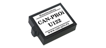
Immobilizer CAN-PROi U122
|
| ⇒ |
|
 | |
The module is an anti-theft device that blocks the vehicle engine via the CAN bus or similar. Small size and lack of additional wiring allow for covert installation anywhere in the car.
|
|
| | Overall dimensions, mm: 26x21x7 |
The immobilizer is controlled using the standard car buttons. The engine blocking, depending on the make and model of the car, is carried out either during its start, or at the moment of movement:
- Start blocking - if there is no input of the sequence of the combination of buttons (PIN-code), the car engine start will be impossible.
- Blocking when starting to move – the engine blocking moment depends on the type of transmission.
In the absence of a sequence of buttons combination, the engine is blocked in the following case:
- with an automatic transmission, the engine will be blocked after shifting from the “P” (“Park”) or “N” (Neutral) position;
- with a manual gearbox, the engine will be blocked after detecting that the vehicle has started moving.
The module is reprogrammable, with a choice of programs for different cars. Has the ability to update software via the Internet.
Immobilizer operation
Switching off and on the CAN-PROi U122 immobilizer
- Switching off(unlocking) – with the ignition on, enter the previously programmed combination of buttons (the indicator on the instrument panel will blink 1 time). The pause between pressing must be more than 0.4 seconds. and should not exceed 5 seconds.
- Turning on(turning on the lock) – occurs after turning off the ignition and opening the door with the ignition off (two flashes of the indicator on the instrument panel).
Service Mode
- Switching on – turn on the ignition and enter the combination of buttons, holding the last programmed button for 10 seconds (confirmation - five flashes of the indicator on the instrument panel). The immobilizer allows you to start the vehicle until the service mode is turned off.
- Switching off – switch on the ignition and enter the combination of buttons, holding the last programmed button for 10 seconds (confirmation - one flash of the indicator on the instrument panel).
Programming a combination of buttons (setting the PIN code)
Option 1:
- With the ignition on, press the gas pedal ten times (if the pedal is supported on the specific vehicle).
- Enter the combination of the supported buttons from 1 to 15. The new PIN-code is saved by turning off the ignition.
- A tuning attempt is ignored if the ignition is not turned off. Entering the procedure for setting up a combination of buttons is indicated by a double flash of the indicator on the dashboard. The indicator used is indicated in the routing.
Option 2:
- With the ignition on, using the SWITCH button, enter the program 11999, the following steps are as in Option 1.
Changing the button combination (setting a new PIN code)
- Enter the previous PIN-code, then follow the steps according to the instructions for setting the PIN-code.
Program number input
The program number is indicated in the immobilizer installation checklist, which can be downloaded here.
Program input:
- Press and hold the SWITCH button until the CAN bus status indicator (LED) starts blinking rapidly, then release the button.
- The LED will start counting down the first digit of the program number with slow flashes, after the required number of flashes, press and hold the button again until the LED starts to flash quickly, then release the button.
- Subsequent program digits (5 digits in total) are entered in the same way as the first digit.
- If the programming is successful, the LED will flash 10 times, confirming the input of the program number. The controller then restarts, signaling with 2 long flashes of the LED.
Checking the program number:
- Press the SWITCH button briefly
- The module will display with slow flashes 5 digits of the entered program number.
- Then the connection status of the six CAN buses of the microcontroller will be displayed (even if the device has access to only two CAN buses). Sequence of LED flashes to indicate the connection status of the six CAN buses:
- 1 LED flash – data transmission via CAN was previously recorded, data is not being received at the moment;
- 2 flashes of the LED - CAN bus is connected, data is being received;
- 3 LED flashes - CAN bus is not connected, connection is required:
- 4 LED flashes - CAN bus not supported, no connection required.
Attention! Checking the number of the entered program is a MANDATORY item of this manual to ensure the correct operation of the system.
|